


Telemetry and Performance in Softwarized Networks
Telemetry and Performance in Softwarized Networks
Call for Contributions
The IEEE Softwarization Newsletter will feature a special topic on Telemetry and Performance in Softwarized Networks for its May 2017 issue.
The transformation of the networking and telecommunication infrastructures with SDN and NFV technologies offers a large spectrum of new capabilities and at the same time introduces its own challenges.
In order to deliver diversifying services with carrier-grade quality, data center operators and network service providers must be able to rely on modern mechanisms and protocols to dynamically provision end-to-end services and monitor their performances in (near) real-time.
While SDN and NFV have made tremendous progress since their inception, there remain gaps and challenges in their deployment and full exploitation in large-scale networks, such as:
-Lack of “quantifiable intent” - getting requirements from customers / service commissioners as to what is the set of performance criteria needed to make the network service “successful”
-The decomposition of such intent through the digital supply chain, including specific requirement towards the SDN / NFV parts of the infrastructure
-The appropriate definition of the assurance mechanisms (measurement, evaluation and verification, accountability...)
To help document and inform our readership about the state of the industry on these matters, the Newsletter is looking for articles pertaining to Telemetry and Performance in Softwarized Networks.
Please contact the IEEE Sotfwarization Newsletter editorial board for your submission: sdn-editor@ieee.org.
OpenState: An Interface for Stateful Packet Processing in Programmable Switches
OpenState: An Interface for Stateful Packet Processing in Programmable Switches
Quentin Monnet, 6WIND
IEEE Softwarization, March 2017
Is it possible to attain better performances and to create new use cases for SDN by moving some of the smartness from the controller to the programmable switches, while keeping an easy configuration interface? This article is a brief presentation of the OpenState abstraction layer [1] concept for stateful packet processing for programmable switching. This abstraction has been designed as part of the BEBA (BEhavioral BAsed switching) project [2], a European research effort funded by the Horizon 2020 program, and dedicated to improving performances through software acceleration as well as enhancing features of programming switches for SDN, by bringing back some of the logics from the controller into the switch using vendor-agnostic solutions.
Stateful packet processing
Concretely, the purpose is to provide the switches with stateful packet processing capabilities: when a packet arrives, it will not be processed solely according to the values contained it its headers (such as the protocol(s) in use, TCP/UDP ports, sender/receiver addresses etc.), but instead the switch will also take into account the packets that were previously received.
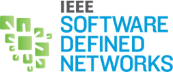
This is easier to understand with a simple example. Let's consider port knocking: this is a basic security method that consists in closing a (TCP|UDP) port on host, until a specific series of packets has been received from the sender. Imagine that the client foo, with IPv4 address 10.3.3.3, wants to connect to the server bar (10.1.1.1) through SSH (TCP port 22).
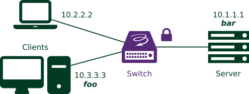
Figure 1: Simple network topology: the clients want to connect to the server through SSH.
The server bar can be directly reached on the Internet, and its administrator does not wish the TCP port 22 to look open to people performing port scans. So, they have enabled port knocking: to open the port to a client, foo for instance, the server must receive from this client a specific sequence of “knocks”. In this example, server bar waits for UDP packets on ports 1111, 2222, 3333, then TCP port 4444, in this order. Once this sequence of packets has been received from a host, the server opens its TCP port 22 for this host, and the SSH connection becomes possible. The graphical representation of this operation, in the shape of a state machine, is represented on the figure below.
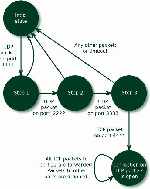
Figure 2: Port knocking state machine
Could we replicate this mechanism inside a switch? All TCP packets from foo and addressed to bar should be discarded, until foo provides the correct UDP packets secret sequence. To recognize the sequence of packets, the switch has to keep in memory the information related to previously received packets belonging to this sequence. In other words, it must implement the state machine associated to port knocking. This is exactly what OpenState permits to do.
OpenState
On a classic SDN network, the switch can identify the packets that are part of the secret sequence, but it cannot tell if this sequence is being executed in the correct order. All those packets would be sent back and forth to the controller, wasting time and resources.
Instead, OpenState brings stateful processing of packets, by proposing an implementation of simplified “eXtended Finite State Machines” (XFSM), also known as Mealy machines [3]. A Mealy machine is an abstract structure comprising a 5-tuple:
- A finite set of states.
- An initial starting state, DEFAULT in the example.
- A finite set of input symbols: the events to match with the packet, such as “TCP dst port = 22”.
- A finite set of output symbols: the actions (“drop”, “forward”, “push/pop a header”, “create a new flow rule” etc.
- A transition function mapping (state, event) pairs into (state, action) pairs.
Concretely, say I am a switch proposing port knocking features: if I am in state STEP_3 and I receive a TCP packet on port 22, I go to a new state, OPEN, and I perform an action: I forward the packet to its recipient. If, on the contrary, I receive any other packet, or if the timeout fires, then the new state will be the initial state, and the action consists in dropping the packet.
How do these machines get integrated to the data plane? The OpenState abstraction layer is implemented by means of two new tables, that replace the former flow table.
The first of those tables is the “state table”.
To each flow pattern, it associates a state key instead of a direct action. The second one is called the “XFSM table”, and to a state and an “event”, it associates an action (to apply to the packet) as well as a new state. OpenState describes the following flow of table manipulations:
- A first step consists in realizing a “state table lookup”. This implies that as a necessary sub-step, the packet is processed by a “key-extractor” that produces a string of bits, which is used as a key to match a row in the state table. The fields taken into account for the creation of this key are the header fields described in what is called the “lookup-scope”. So, once we have the key, we search the state table: this lookup returns the current state for the flow the packet belongs to.
- For the second step, this returned state is appended to the key, and a second lookup is performed, this time in the XFSM table. It matches both on the state and on the packet metadata, and returns an action indicating what to do with the packet, as well as a new state.
- The final step consists in updating the state table with the new value. To do so, the key is processed by another key extractor, the “update scope”. At the end of this process, the table contains the new state for the flow.
Not counted in the three steps is also the execution of the action returned by the XFSM table, that is used to actually process the packet.
Let’s see now what it gives with the port knocking example:
- SSH from 10.1.1.1 is allowed.
- SSH from 10.2.2.2 to 10.1.1.1 is allowed.
- SSH from 10.3.3.3 to 10.1.1.1 is initially forbidden, but can be allowed after the client at 10.3.3.3 sends the correct sequence.
In this setup, at a given time, the traffic from each host is in one of the following states:
- DEFAULT: no SSH allowed.
- OPEN: SSH traffic (TCP towards port 22) is allowed.
- STEP_1; or STEP_2, or STEP_3: the port knocking sequence is ongoing.
For 10.1.1.1 and 10.2.2.2, the state is always OPEN. But for 10.3.3.3, it depends on the progress of the secret sequence, so the state may evolve. Thus, the state table itself can evolve, without the intervention of the controller: the switch tracks the succession of states.
For instance, assuming that 10.3.3.3 has sent the first packet of the sequence (UDP on destination port 1111), the switch starts with the first step: state table lookup. The state table is as follows (when searching for a match, the tables that are provided here are scanned from top to bottom, so the packets not matching any other pattern will be assigned the DEFAULT state by the last flow pattern):
Figure 3: State table, when in DEFAULT state.
But how exactly are these states expected to evolve? All the next possible steps are in the XFSM table. So the switch carries on to the second step, and performs an XFSM table lookup. This table, depicted below, has two main blocks: “Flow matching pattern” and “Actions”.
The former is subdivided into two columns: “State” and “Event”. The matching row is the one for which the first (State) column is matched by the current flow state (e.g. STEP_1) and the second (Event) column is matched by the packet (e.g. TCP dst port = 2222).
The second block of columns gathers two columns, “Action” and “Next state”. Once the matching row has been determined with the state and events associated to the packet, the corresponding action, found in the third column, is applied (e.g. Drop).
Here is the XFSM table coming with our example port knocking use case:
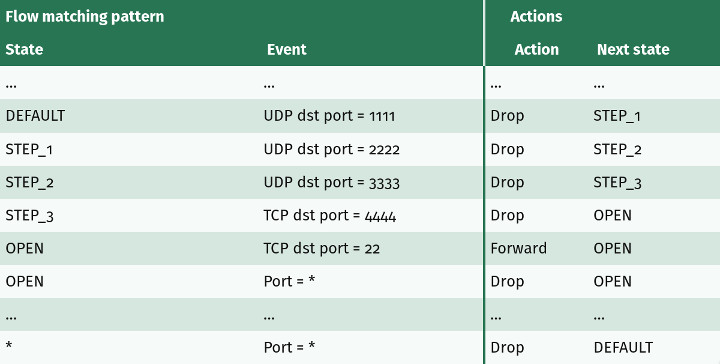
Figure 4: XFSM table.
At last, the state table update occurs. The state for the flow of the packet is modified, as indicated by the state name found in the Next state column.
Let’s connect the three steps: if the first packet of the sequence has been previously received (the state is STEP_1), and a new packet from host 10.3.3.3 is received, the State table is scanned first. The third row from the top is hit. It returns state STEP_1, and this information is used to search the second table. Two cases:
- The event on row 2 is matched: the packet is a TCP packet, with destination port = 22.
- The packet is anything else, and the very last row is matched instead.
If the packet received is not a TCP packet towards port 22 (second case) then the packet is dropped, and the state is moved to DEFAULT. As a consequence, the port knocking sequence is “reset”.
If, on the contrary, the packet targets TCP port 22, the packet is dropped all the same, but the state for this flow—the flow of packets sent from 10.3.3.3 to 10.1.1.1—is changed to STEP_2. This means that the State table is modified, and now looks like this:
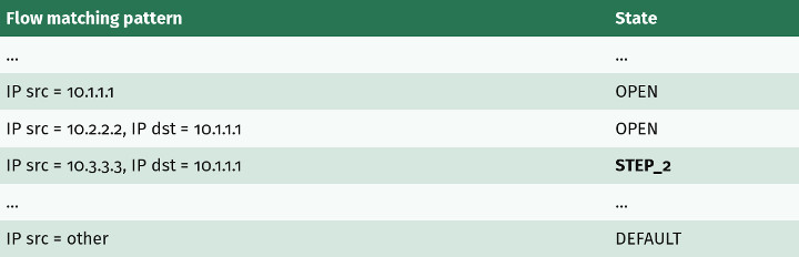
Figure 5: State table, when in STEP_1 state.
The next packet from 10.3.3.3 will match the third row again, but this time it will return STEP_2, so the switch will look for a different row in the XFSM table. If again a new packet from the port knocking sequence is received, the state will move to STEP_3, and ultimately to OPEN.
Leveraging OpenState
These were the main lines of OpenState. With a similar setup, it is possible to implement many applications relying on stateful processing, including load balancing, failure detection and recovery, in-switch ARP handling, middlebox or distributed protection against DDoS, and others [5 (D5.1, D5.2)]. BEBA research project heavily relies on this concept, and goes further. Some related items include:
- Hardware proof of concept of OpenState abstraction layer [4].
- OpenState can be extended with per-flow registries and conditions. This is called Open Packet Processor [5 (D2.3)].
- Software acceleration of switches running the OpenState layer [5 (D3.3)].
- Development of a reference implementation of the interface (switch and controller) [6].
Regarding the BEBA project as a whole, it entered its final phase. This is the interesting part, with results coming from different sizes:
- The performance tests are providing the first results. While the final benchmarks are not finished at this time, we know that the software acceleration effort performed on the reference implementation (based on ofsoftswitch, and accelerated with the PFQ framework) runs at nearly 90 times its initial speed.
- OpenState is envisioned to be integrated into industrial products, although no public announcement has been made this far.
- Regarding standardization, OpenState is being pushed as an OpenFlow extension at the ONF. The proposal is actually undergoing some changes to address minor issues.
Hopefully, it will help deploy a variety of stateful applications for even faster SDNs!
References
- [1] OpenState: G. Bianchi, M. Bonola, A. Capone, and C. Cascone, “OpenState: Programming Platform-independent Stateful OpenFlow Applications Inside the Switch” ACM SIGCOMM Computer Communication Review, vol. 44, no. 2, pp. 44–51, 2014 (link).
- [2] BEBA project web page.
- [3] Mealy machines: definition on Wikipedia.
- [4] Hardware implementation: S. Pontarelli, M. Bonola, G. Bianchi, A. Capone, C. Cascone, “Stateful Openflow: Hardware Proof of Concept”, IEEE HPSR 2015, Budapest, July 1−4, 2015 (link).
- [5] BEBA's list of public deliverables (link). In particular, deliverables D2.1 and D2.2 relate to the design and basic implementation of the OpenState layer.
- [6] Reference implementation of BEBA switch, on GitHub.
Quentin Monnet joined 6WIND as a R&D Engineer in 2015, and works on high performance networking software. Just before that, he defended his PhD thesis about security against DoS in sensor networks at “Université Paris-Est”, France. He is involved in European research projects about fast and flexible packet processing, and has been modestly contributing to several open-source projects.
Editor:
 Marie-Paule Odini holds a master's degree in electrical engineering from Utah State University. Her experience in telecom experience including voice and data. After managing the HP worldwide VoIP program, HP wireless LAN program and HP Service Delivery program, she is now HP CMS CTO for EMEA and also a Distinguished Technologist, NFV, SDN at Hewlett-Packard. Since joining HP in 1987, Odini has held positions in technical consulting, sales development and marketing within different HP organizations in France and the U.S. All of her roles have focused on networking or the service provider business, either in solutions for the network infrastructure or for the operation.
Software-Defined Perimeters: An Architectural View of SDP
Software-Defined Perimeters: An Architectural View of SDP
Daniel Conde
IEEE Softwarization, March 2017
Introduction
Software Defined Perimeters (SDP) is an emerging security architecture that restricts network access and connections between allowed elements. With origins in the defense IT infrastructure and spreading to enterprise use, it promises to help mitigate a broad set of security vulnerabilities that afflict IT infrastructure protected by conventional perimeter security. SDP serves to identify the source and destination of a network connection and assumes there is no trust between potential participants and a secure connection is only granted when explicitly permitted.
History
Software Defined Perimeters draws on the Defense Information Systems Agency (DISA)’s black cloud that restricts connections only to those with a need to know basis. It was then popularized by the Cloud Security Alliance’s SDP Working Group for creating highly secure and trusted end-to-end networks for broader enterprise use.
The term “Software Defined” has been popular but often lacks a clear definition. It has been used in many contexts such as Software Defined Network (SDN), Software Defined Wide-Area Network (SD-WAN), or Software-Defined Data Center. This column helps show where Software Defined Perimeters draws upon similar concepts, its history and where it innovates.
The concepts are not new, and there are predecessors such as network access control (NAC) that restricted client end-point devices to connect to networks. It uses concepts found in Software Defined networks, such as the separation of the data plane for communications from the control plane. The SDP concept is useful for servers and client endpoints, and may be used in clouds as well as in traditional data centers. SDP combines many of these elements to create a new architecture.
SDP is not a replacement for existing solutions, but an architecture that complements and builds upon existing solutions such as SDN.
Principles
From an IT infrastructure perspective, as opposed to a security viewpoint we can distill the SDP concepts into these principles. In this column the word “hosts” is used, although that includes client end-points.
- Separation of the control plane from the data planes. Ability to control access is managed separately from the transmission of data. This means that permission is separated from access, and makes data transport independent and enables each part to be managed and grow separately. Control plane is handled by an SDP controller.
- Separation of the logical and physical components. Related to (1), the connections between hosts are virtualized using overlay tunnels that represent logical connections that traverse a physical network. This enables communications to be secure and not restricted to physical topologies.
- Authenticating the hosts. Only those elements that are authorized will be able to participate in communication.
- Validating the hosts against a set of policies that determines whether or not security constraints are met. This includes verifying the hosts for absence of malware, only allowed applications can connect, or other business policies such as time of day when connections are allowed, or other external signals such as threat-intelligence data.
How it differs from traditional security
Traditional perimeters security protects against external attacks and access. This no longer works if intrusions compromise elements inside the external perimeter. Rather than using a default of not trusting external access and trusting access inside the security perimeter, SDP trusts no-one as a default, and admits access on a case-by-case basis.
SDP works across resources as varied as traditional end-points, data centers or clouds, since overlay tunnels can traverse different types of infrastructures. Hosts gaining access may include traditional PCs, mobile devices, or even Internet of Things (IoT). Locations may include public clouds, data centers, traditional campus networks or remote offices. Resources may include cloud services (exposed via REST APIs) or traditional client-server data center apps accessing applications or data.
The Cloud Security Alliance (CSA) lists these deployment modes for SDP.
- Client-Gateway – SDP uses a proxy that arbitrates connections between clients and a set of protected servers. A client connects to a gateway which in turn provides access to hosts that provide services.
- Client-Server – there is no gateway proxy sitting between the client and server. The clients directly connect to the hosts.
- Server to Server – used for servers offering services (via REST APIs) to applications.
- Client to Server to Client – peer to peer connections between clients.
For hosts to initiate a connection the following workflow steps are necessary. The CSA white paper lists 7 steps, but we use a simplified edition since we assume that the SDP infrastructure is already brought up:
- Authenticate hosts that initiate connections, and receiving connections to central controllers.
- Each host identifies only the hosts it can communicate with.
- Validate the hosts against security policies (host type, malware checks, time of day, etc.)
- Connect the hosts using a Virtual Private Network (VPN) tunnel to allowed accepting hosts.
These steps, while seemingly simple, accomplish many goals for security in an elegant way since they provide for these benefits:
- Partitioning of the network. This is like micro segmentation seen in software-defined networking today.
- Reducing the attack surface. If the resources are not exposed through conventional means (known host names, IP addresses, etc.) and access is arbitrated by a controller, then the potential security targets are not known, reducing the opportunity for attacks such as Distributed Denial-of-Service (DDOS), Man-in-the-Middle or Advanced Persistent Threats.
- Unify security between cloud and other non-cloud resources. Developing a uniform security model that extends from on-premises data centers to cloud resources is difficult using conventional network security methods. Abstracting the network transport via overlay tunnels creates a set of connections that spans different deployment models – whether cloud-hosts, on-premises data centers, or remote offices. This enables the use of uniform model for network connections that allows the use of network security controllers that enforces policies.
Potential Challenges
A complete SDP solution cannot be slipped into an existing infrastructure without some disruptions in the network and software infrastructure. Applications and operating system configurations need to be aware of SDP to access SDP workflow and secure tunnels. The presence of a controller means there is another element for networks to rely on, and it needs to be secured and be made highly available.
These challenges can be overcome. SDPs use conventional IP networks and does not change the fundamental architecture of layer 2 through 7 networking. Existing network and security management and monitoring tools and operational procedures may need to change if conventional security methods are replaced by SDP.
Commercial and open source solutions
Commercial and open source solutions provide SDP. Products from Vidder and CryptZone market SDP solutions. Existing products provide for key elements found in SDP, such as Cisco ACI (and a similar open source project, Group Based Policy), VMware NSX, Nuage VSP. Google has published its BeyondCorp efforts that shares these concepts. Cisco, HPE, Juniper offer NAC solutions that also offer SDP-like elements. Service providers such as Verizon Enterprise have started to embrace these concepts. The zero trust network concepts are adopted by many security or network gear vendors.
Conclusion
SDP promises to solve many security challenges. The architecture leverages existing technologies, such as VPN tunnels, combines it with modern concepts from SDN and micro segmentation to provide an architecture that shows promise for solving many security problems. It has demonstrated success in military security and may be extended for commercial and enterprise deployments. It shows promise in cloud based applications that fundamentally exhibit distributed deployment models and do not fit into a traditional perimeter security model.
References
Department of Defense Global Information Grid Architectural Vision, http://www.dtic.mil/cgi-bin/GetTRDoc?AD=ADA484389
Software Defined Perimeter Working Group, https://cloudsecurityalliance.org/group/software-defined-perimeter/
 Daniel Conde is an analyst covering distributed system technologies including cloud computing and enterprise networking. In this era of IT infrastructure transformation, Dan’s research focuses on the interactions of how and where workloads run, and how end-users and systems connect to each other. Cloud technologies are driving much of the changes in IT today. Dan’s coverage includes public cloud platforms, cloud and container orchestration systems, software-defined architectures and related management tools. Connectivity is important to link users and applications to new cloud based IT. Areas covered include data center, campus, wide-area and software-defined networking, network virtualization, storage networking, network security, internet/cloud networking and related monitoring & management tools. His experience in product management, marketing, professional services and software development provide a broad view into the needs of vendors and end-users.
Editor:
 Francesco Benedetto was born in Rome, Italy, on August 4th, 1977. He received the Dr. Eng. degree in Electronic Engineering from the University of ROMA TRE, Rome, Italy, in May 2002, and the PhD degree in Telecommunication Engineering from the University of ROMA TRE, Rome, Italy, in April 2007.
In 2007, he was a research fellow of the Department of Applied Electronics of the Third University of Rome. Since 2008, he has been an Assistant Professor of Telecommunications at the Third University of Rome (2008-2012, Applied Electronics Dept.; 2013-Present, Economics Dept.), where he currently teaches the course of "Elements of Telecommunications" (formerly Signals and Telecommunications) in the Computer Engineering degree and the course of "Software Defined Radio" in the Laurea Magistralis in Information and Communication Technologies. Since the academic year 2013/2014, He is also in charge of the course of "Cognitive Communications" in the Ph.D. degree in Applied Electronics at the Department of Engineering, University of Roma Tre.
The research interests of Francesco Benedetto are in the field of software defined radio (SDR) and cognitive radio (CR) communications, signal processing for financial engineering, digital signal and image processing in telecommunications, code acquisition and synchronization for the 3G mobile communication systems and multimedia communication. In particular, he has published numerous research articles on SDR and CR communications, signal processing applied to financial engineering, multimedia communications and video coding, ground penetrating radar (GPR) signal processing, spread-spectrum code synchronization for 3G communication systems and satellite systems (GPS and GALILEO), correlation estimation and spectral analysis.
He is a Senior Member of the Institution of Electrical and Electronic Engineers (IEEE), and and a member of the following IEEE Societies: IEEE Standard Association, IEEE Young Professionals, IEEE Software Defined Networks, IEEE Communications, IEEE Signal Processing, IEEE Vehicular Technology. Finally, He is also a member of CNIT (Italian Inter-Universities Consortium for Telecommunications). He is the Chair of the IEEE 1900.1 WG on dynamic spectrum access, the Chair of the Int. Workshop on Signal Processing fo Secure Communciations (SP4SC), and the co-Chair of the WP 3.5 on signal processing for ground penetrating radar of the European Cost Action YU1208.
Ensuring QoS with In-Home Wi-Fi Performance Monitoring
Ensuring QoS with In-Home Wi-Fi Performance Monitoring
Metin Taşkin, CTO and Co-Founder, AirTies
IEEE Softwarization, March 2017
How operators are using real-time and historical performance data across managed and unmanaged devices
The proliferation of Wi-Fi connected devices, combined with the increase in video streaming, is straining in-home Wi-Fi networks. Factors including types of devices being used, distance to the nearest in-home access point (AP), and home construction materials are just some of the issues preventing subscribers from experiencing broadband speeds consistently throughout the whole home. And, operators have limited visibility into the home Wi-Fi network beyond the router/gateway to understand what is actually happening in real-time in subscribers’ homes.
As operators face mounting pressure to ensure that Wi-Fi can deliver the full speeds and range of broadband and video services within the home, they need the ability to fully monitor and manage the in-home Wi-Fi network itself.
In-Home Wi-Fi Challenges
The preeminent WLAN technology, specified by the IEEE 802.11 standard, is now associated with a global Wi-Fi market that reached $15 billion in 2015 and is estimated to more than double by 2020.[1] While it has transformed consumer electronics and public behavior, it has also become a victim of its own success, especially in consumer’s homes.
Each subsequent release of 802.11 has boosted Wi-Fi performance, but the variety of implementations and equipment has led to inconsistency in QoS. Meanwhile, Wi-Fi has become a leading source of trouble tickets for operators – and may account for more than half of all call-center traffic.
A related problem is that service providers must resolve these calls with limited visibility. Despite massive investments to get faster broadband speeds to the home, MSOs have rudimentary tools to see within. Simple network management protocol (SNMP) and TR-069 offer basic support. Yet beyond rebooting the gateway, changing its channel assignments, and restoring or updating its settings, there is little else that operators can do to the extensive network of unmanaged devices beyond their range of view.
The home itself can also pose problems. Some construction materials impede the flow of Wi-Fi signals, and interference from appliances is another issue. Total square footage may exceed coverage, especially in higher frequencies. These impediments, combined with the demands of video, have led many consumers to take action. Some buy new routers. Many invest in Wi-Fi extenders or repeaters. But, these solutions often create problems of their own.
Technology Issues
Few consumers know the technical details of Wi-Fi or its various implementations – but most of the issues that they face are technical, including:
- Standards: At its base, Wi-Fi is a series of variations on a standard. Just to name three: 802.11ac operates in the 5 gigahertz (GHz) band; 802.11n, in both 5 GHz and 2.4 GHz; and 802.11g, in 2.4 GHz alone. Both “ac” and “n” devices use multiple-input multiple-output, orthogonal frequency division multiplexing (MIMO-OFDM) but “g” devices use only OFDM. These and other differences can impact performance.
- Speeds and range: The 5 GHz band along with the greater channel options of “n” and “ac” yield much greater throughput than earlier standards. However, advertised speeds may overstate the case. The protocol overhead and interference in operating channel result in much lower actual throughput than advertised speed. Meanwhile, while higher frequencies are usually faster, they are less able to penetrate objects or traverse distance. Conversely, moving a device away from the home’s main router can negatively impact the performance of every device.
- Repeaters: These devices cause trouble about half the time. They may suffer from a poor link with the AP or router, meaning that a client links up with a strong repeater, but ends up with very low speed.
- Sticky clients: Mobile or tablet clients are “sticky” when they retain their connection to a particular AP, even if the signal strength has dropped significantly or a better device is closer. By hogging the available airtime, these slow-performing devices may degrade the overall performance for all other devices in the home.
These issues tend to overlap. The shorter range of the more advanced – and faster – “ac” standard, for example, may lead a consumer to purchase a repeater; yet that device could be inadequately connected to the AP or attract clients that won’t let go.
Ensure QoS with Performance Monitoring
A good answer to these challenges is Wi-Fi Mesh, which combines devices, PHY (physical layer) technologies and software. By definition, Mesh enables alternate routes. In-home, that translates to a Wi-Fi router/gateway, along with two or more APs. Wi-Fi Mesh software can also be ported onto other devices, such as IP-enabled set-top boxes or DVRs.
The addition of APs extends the reach of Wi-Fi signals, potentially eliminating dead zones. But unlike repeaters, multiple Mesh APs manage mobile clients to connect at their maximum capability. It does so several ways. One is by treating multiple PHYs, 802.11 Wi-Fi and Ethernet, power line communications (PLC) and Multimedia over Coax Alliance (MoCA), as individual point-to-point Mesh connections.
The primary driver of Wi-Fi Mesh performance, however, is routing software. Similar to how IP packets are routed across the Internet, traffic on a Wi-Fi Mesh network is routed by algorithms that determine the best path. The Mesh operates logically as a single service set identifier (SSID) and continuously calculates routes according to the number of active devices, the traffic profile and any QoS required by the subscriber’s agreement with the service provider.
This kind of smart routing also enables client steering. Instead of a gateway/router using its limited perception of interference, a Wi-Fi Mesh network taps into clear channel assessment (CCA) data and collects information from all APs before making that selection.
Wi-Fi Mesh also exposes large quantities of data, making it possible to create a remote monitoring platform using intelligent APs to collect and share key Wi-Fi performance data from all devices. This type of dashboard offers engineers and operations staff a range of information, including:
- Real-time and historical data on active Wi-Fi connections, traffic and throughput (figure 1)
- Band connection durations of all clients (figure 1)
- 5 GHz vs. 2.4 GHz connection rates and client steering occurrences (figure 1)
- Airtime consumption (figure 1)
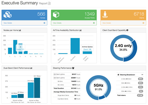
Figure 1
- In-home Topology with number of APs, connection rates of wireless APs and third-party devices (figures 2 & 3)
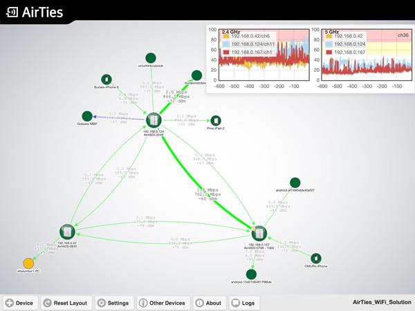
Figure 2
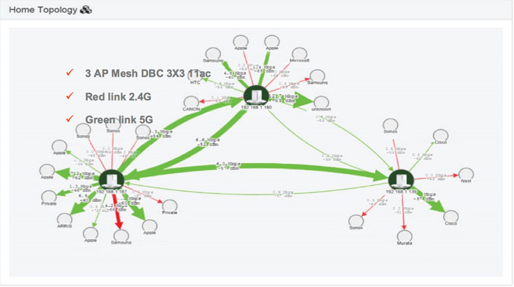
Figure 3
- Distribution of 802.11g, 802.11n or 802.11ac clients/devices (figure 4)
- Speed capability and distribution of client brands (figure 4)
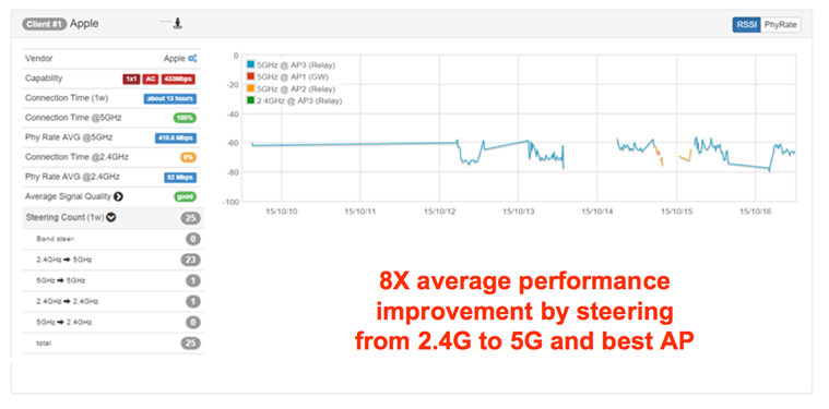
Figure 4
Conclusion
Consumers who are using more Wi-Fi devices than ever have a reasonable expectation that wireless performance within the home should be as good as the broadband service delivered to the home. When that proves not the case, many contact their service provider or opt to buy and install new Wi-Fi routers, repeaters or extenders – which often leads to more trouble calls, forcing more truck rolls, because the operator has little to no visibility into the home, beyond the managed router/gateway.
Already having invested significantly to improve broadband services and address new growth opportunities in the gigabit home, operators are undergoing a dramatic re-thinking of their in-home Wi-Fi technology and monitoring capabilities. Operators recognize that their subscribers often do not delineate between Internet delivery and Wi-Fi, and thus are focused on new efforts to improve the customer experience across managed and unmanaged devices within the home.
[1] “Global Wi-Fi Market by Business, Product, Service, Vertical, Regional- Global Forecast to 2020,” Market and Markets, July 2015.
 Metin Ismail Taşkın, Chief Technology Officer, AirTies.
After working as a research engineer at the National Metrology Institute of the Scientific and Technical Research Council of Turkey (TUBITAK), Taşkin continued his career in the United States: first at Hittite Microwave Corporation in Boston MA, designing radar and microwave communications system, and later at CISCO Systems in San Jose CA, in the Wireless Access Business Unit where he developed fixed wireless access devices. Taşkin was responsible for system design outdoor wireless base station and subscriber devices providing wireless internet access. Taşkin then joined the Wireless Networking Business Unit of CISCO as a system architect. He led team of 25 engineers that developed BR1410, an IEE 802.11a compliant Wireless Outdoor Bridge. Taşkin received the “CISCO Innovator” award for a successful design and development of this product. Taşkin moved back to Turkey to join the founding team of AirTies and currently works as the company’s Chief Technology Officer.
Metin Taşkin has a Bachelor’s degree in Electrical and Electronics Engineering and Master’s degree in Biomedical Engineering from Bosphorus University in Istanbul.
Editor:
 Eliezer Dekel is a Chief Architect for Huawei Technologies Corporate Reliability Department. He is researching RAS for SDN and NFV. He retired from IBM Research - Haifa, as a Senior Technical Staff Member and Chief Architect for Distributed Systems. In his this role he focused on developing infrastructure technologies for very large scale distributed systems.
Eliezer Dekel is the editor in chief of EAI Endorsed Transaction on Cloud Systems. He is also an Associate Editor for ACM Computing Surveys and a member of the editorial board for IEEE SDN Newsletter. Eliezer served on numerous conference program committees and organized, or served as chair in some of them. He has been involved in research in the areas of distributed and fault-tolerant computing, service-oriented technology, and software engineering. He was recently working on technologies for providing Quality of Service, with a focus on dependability, in very large scale multi-tier environments. For this area he initiated together with colleagues the very successful International Workshop on Large Scale Distributed Systems and Middleware (LADIS). This workshop, sponsored by ACM. It was one of the first workshops to focus on the foundations of "cloud computing." He was an organizer of CloudSlam'09 the first cloud computing virtual conference. Eliezer was also involved in several EU FP7 ICT funded projects.
Eliezer has a Ph.D. and M.Sc. in computer science from the University of Minnesota, and a B.Sc. in mathematics from Ben Gurion University, Israel. Prior to joining IBM Research - Haifa, Eliezer served on the faculty of the University of Texas at Dallas computer science department for more than ten years.
We Want to Hear From You!
We Want to Hear From You!
Laurent Ciavaglia, Editor-in-Chief, IEEE Softwarization Newsletter
IEEE Softwarization, March 2017
As Editor-in-Chief of the IEEE Softwarization Newsletter, I invite you, our readers, to participate in a brief survey as we strive to inform and advance Software Defined Networks and virtualization related technologies.
Our aim is to provide the professional practitioner, as well as the casual observer, with excellent knowledge in a concise, readable, and practical format. We encourage you to take a few minutes to let us know the value and benefits you find in reading our bimonthly publication.
LINK TO THE SURVEY: http://bit.ly/SDNnewslettersurvey
Thank you for your ongoing support and participation.
We look forward to continuing to provide the very best of content to the industry we serve.
 Laurent Ciavaglia
Editor-in-Chief, IEEE Softwarization Newsletter
LinkedIn profile